
Posted:
Modified:
This article is a translated and revised edition of two previous articles in Dutch: Procesconcepten in NORA and NORA processen en ArchiMate.
Table of contents
The NORA (Dutch Government Reference Architecture) defines a number of concepts regarding processes that might also be useful outside of the Dutch government context for which NORA was originally intended.
In this article, I would like to discuss the definitions of:
- Chain process
- Business process
- Work process (Sub-process)
NORA defines the concepts correctly, but summarily, and in my enterprise architecture practice I encounter common errors. In this article, you will learn how to model chain processes, business processes, and work processes in accordance with NORA, in ArchiMate and BPMN.
Definitions
First of all, it is important to realize that the terms were defined in NORA 2.0, but were (partially) abandoned in the later version 3 (2014 ). There is an important reason for this, namely that the definitions were too rigid. An explanation of this will follow shortly. However, within various Dutch government organisations, the definitions have been embraced and used in process architectures (such as in GEMMA ), and it is important that we clearly define what we mean by this and how we should deal with it. In my work at UWV, the Tax and Customs Administration, and the Ministry of Defence (among others), I encounter the same struggle.
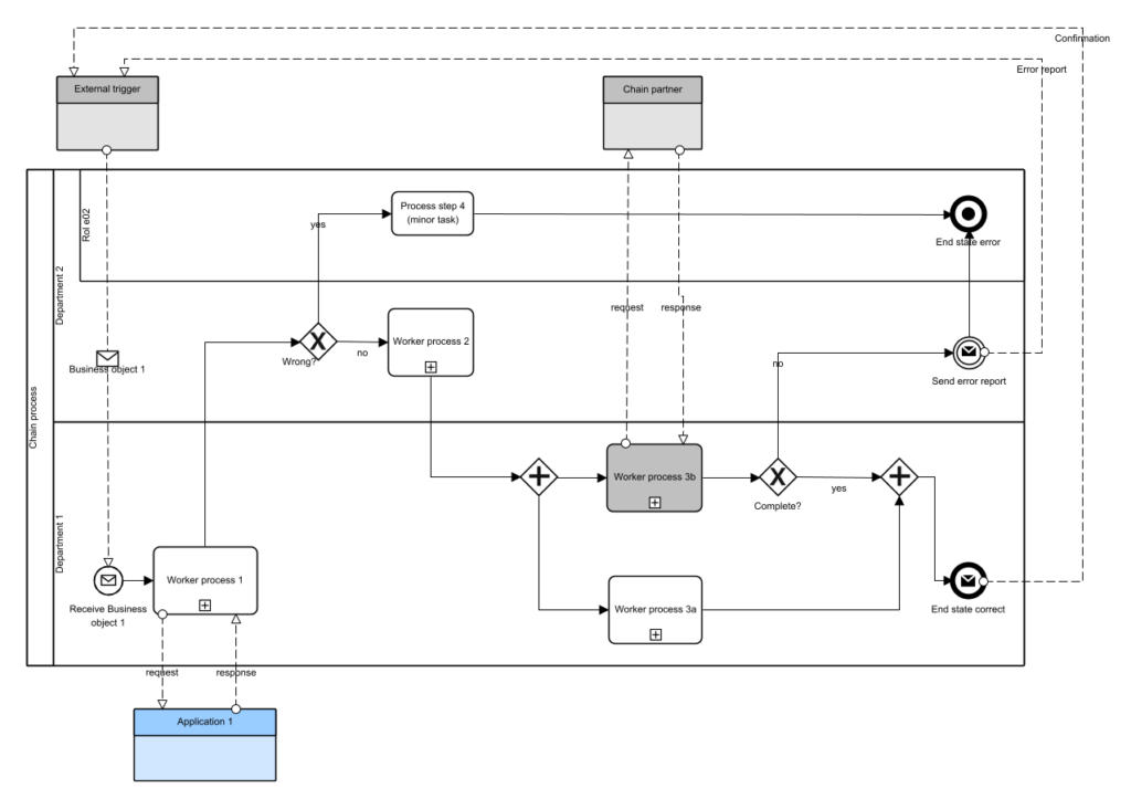
We will use the generic process model above as a framework for the explanation:
| Concept (NORA 2.0) | Definition |
| Chain process | A business process under the control/responsibility of the own organisation, in which at least one activity is performed by a chain partner, under the direction of the own organisation. |
| Business process | An end-to-end (customer-to-customer) top-level process that delivers a specific service to a stakeholder. |
| Work process or sub-process | An activity as part of a (usually but not necessarily top-level) business process that is carried out by one part or department of the organisation |
| Process step | An activity as part of a (usually but not necessarily level-1) business process that is performed by one role |
| Action | An activity as part of a business process that is performed by one person or system |
Supply chain process analysis
Diagram 1 shows a generic example of a top-level business process. The fact that this top-level process is a chain process is immediately visible in this diagram, because one step in the process ( Work Process 3b ) is entirely outsourced to a chain partner (Chain Partner, the black-box pool with which a response/request message flow interaction is visible).
This does not always have to be an activity in a top-level diagram: whenever, on any process level, a process step or action is outsourced, the top-level process still constitutes a chain process: a part of the process, at whatever process level, is outsourced to a chain partner under the direction of the own organisation .
What is the difference compared to a “regular” partner, for example, a payment process step that is outsourced to a payment provider?
The payment provider will also be modelled with a black-box pool, but is not a chain partner. In BPMN terms, the payment provider is a “regular” collaborator participating in the process. There will also be message flow interactions between the collaborator’s black-box pool and its own white-box pool. However, our own organisation has no dependency whatsoever on the internal structure and design of the black-box pool process. The payment provider makes a service interface available to all users (of which we are one), and we must conform to that interface in order to be able to use the payment provider’s services. The message flow interactions take place from our “own” activities with message send/receive elements (tasks or events).
With a chain partner, the situation looks slightly different. We do model a “local” placeholder for the outsourced activity. However, because we are in control (we are the process owner), we are able to impose all kinds of requirements on that local placeholder. For example, we can make statements about how the activity is triggered (incoming sequence flow) and the same for the outgoing sequence flow(s). If we wish, we can describe the internal structure of the (externally executed) process. We act as the owner of the outsourced activity, and the dependency is therefore much greater than in a “regular” collaboration. The Work Process 3b activity is therefore actually “our” activity, performed under our auspices by a partner organisation. Because there is something special about it, I am using a gray shade of the block, but this has no specific meaning and is a personal preference (you also see a blue black-box pool; more on this later).
In summary: to do justice to the tighter dependency on a process step executed by an external organisation under our own direction, I propose using a local placeholder with message flow connections to the external organisation.
I want to explore the diagram a bit more.
Only top-level work processes?
We see that all activities except one are subprocesses (as indicated by the plus sign in the activity). Below, I will show the content of those subprocesses. However, one activity has been included (as an example) that is not a subprocess but a regular (Abstract) Task: Process Step 4. This can be a simple action of, for example, just one step. It occurs at this process level, and because an action in the definitions above is linked to a role within a department/team, that information is also shown here: the role Role 02 within Department 2 .
You can also choose to display only work processes at the top level. In that case, you have little choice but to make Process Step 4 a subactivity of a Work Process 4 that you display at the top level. Both are possible.
Let’s walk through the process.
Walk-through
The process is triggered by an External trigger (black-box pool, for example a Customer ). This is the case in the majority of business processes. The incoming request is designated by Business Object 1 , the message payload of the triggering message flow. An example of such an object could be an Order. We then say that the business process as a whole represents the “Order”. Business processes usually have one (and only one) business object that represents the process.
Next, Department 1 executes a process designated as Work Process 1. We see that this is a subprocess, and we observe an outgoing and incoming message flow (resp. request/response) with an external black-box pool. This pool is tinted blue here, which is a personal convention (inspired by ArchiMate, where application objects are blue). I recommend modelling application connections using black-box connections. Why?
- Applications are encapsulated (ideally – service components developed nowadays instead of applications are so by definition), and therefore independent of the outside world. They should be seen as service providers.
- Applications are used in a process via some API. This maps perfectly to the message flow concept, especially when asynchronous communication takes place (more on (a)synchronous later).
- The user/client of an application has no dependency whatsoever on the internal structure of the application.
We will dive deeper into what happens within Work Process 1 shortly. Therefore, I am not in favour of including the application as a Lane in the process, but advise modelling it as an external black-box pool.
We see that Work Process 1 is followed by an XOR Gateway. From this, we can deduce that the Work Process 1 subprocess has two end states, one of which is labeled Error (Gateway labeling convention). Below, we will explicitly describe this process level; for now, we will briefly walk through the process at this top level.
If there is an Error end state in Work Process 1, a small action must still be performed by Role 02 in Process Step 4, after which the process ends in the End state error state. With that, the process ends (there are no more tokens in the process).
If there is no faulty end state, Work Process 2 is executed, the inner workings of which we describe in more detail below. After this step, we arrive at a split (Parallel Gateway) that ensures Work Processes 3a and 3b are executed in parallel. Work Process 3b is the local placeholder for work that is actually performed by the Chain Partner. We will zoom in on the steps in this subprocess below.
After Work Process 3b is completed, a gateway follows: we can already see here that Work Process 3b has two end states, one of which is labeled Completed. If this is confirmed (happy flow, the yes-gate is triggered), the merging parallel gateway waits until Work Process 3a is finished. As soon as this is the case, both tokens are merged, the process proceeds to End state correct, and the process ends. If Work Process 3a finishes before Work Process 3b, the merging gateway waits until Work Process 3b is finished, merges the tokens, and then also proceeds to End state correct .
However, if Work Process 3b does not end in the Completed end event , an error message is sent to the External trigger, and the process enters a Terminate end event error. This must be a Terminate end event (and not, for example, a Message Send end event) because there is parallelism in the process: Work Process 3a might not be finished yet. The Terminate end event ensures that Work Process 3a , should it still be in progress, is terminated, and the entire process ends in an End state error .
So much for the top-level process. Let’s now zoom in on the subprocesses.
Work process 1
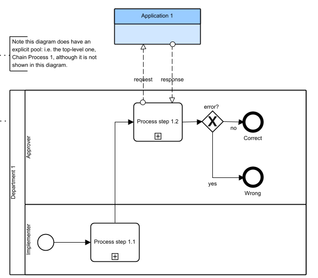
In this subprocess, we see two sub-lanes within the Department 1 lane : that of the Executor ( which executes Process Step 1.1 ) and that of the Approver, which executes Process Step 1.2. I will not go into this subprocess further and will immediately zoom in on Process Step 1.2 .
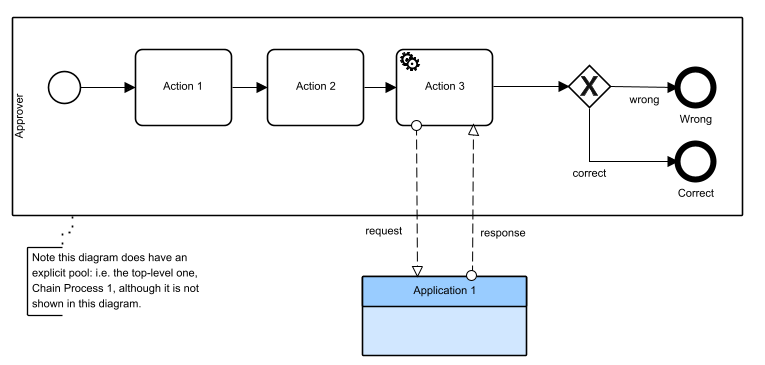
At this process level, we see one example of the two ways application connections can be modeled in process models, namely by using a Service Task. Action 3 is the step executed by Application 1. We see the message flow interactions originating from that service task. Note that the use of a Service Task implies that the interaction takes place synchronously , whereas the message flows suggest that it takes place asynchronously . Recently, we have seen a convention emerging to model asynchronous service interactions using a service task and message flows anyway, when the request/response cycle is very short (nano/milliseconds). For an example of asynchronous interactions, see Work Process 3bbelow .
For the sake of clarity: this sub-process does not (yet) contain sublanes that describe the sub-roles/persons within the Approver role (for example, to indicate that Action 1 is performed by Junior Approver ).
Note also that all message flow interactions propagate upwards from the lowest level (in this case, Act 3 ) to the top level.
Work process 3b
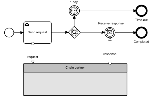
Although this subprocess does not involve an application connection but one with an external chain partner, note that the connection pattern is the same.
We see that we are not doing anything in this process; everything is delegated to the Supply Chain Partner via asynchronous message flows. We also see a timeout on the process, a standard part of any external delegation.
We also see another pattern: the send is a task, and the receive is an event. This allows us to, for example, set a loop on the send or attach a boundary event to it (for example to handle errors).
BPMN™ and ArchiMate®
The rest of this article focuses more on enterprise architects. There, too, I often see a struggle to do this in line with the NORA reference architecture, and to understand exactly what NORA meant by the distinction between business processes and work processes. We encounter this time and again with the various derived reference architectures such as GEMMA , HORA, etc. (for an overview, see: Overview of NORA Family Architectures )
Note that in the latest version of the NORA, partly due to the many misunderstandings that arose around these concepts, this distinction has been abandoned.
As a more mature architecture discipline emerges within those organisations, it naturally should not stop there. After all, from the perspective of enterprise and business architecture, we also describe processes. For this, ArchiMate, a modelling language for enterprise architecture, is predominantly used.
Enterprise Architecture
The field of enterprise architecture is maturing. The foundation for this largely comes from the Business Architecture Guild. This is an independent organisation whose work is adopted by the Open Group in TOGAF (Phase B: Business Architecture). This, in turn, is reflected in ArchiMate, as both standards are managed by the Open Group and are aligned with each other. ArchiMate is one way to describe the metamodel for TOGAF. There are others, but globally, and certainly in the Netherlands, ArchiMate is the only one I encounter.
The four pillars of enterprise architecture
According to the Guild framework, there are four pillars on which enterprise architecture rests:
- Capabilities
- Value Streams
- Information
- Organization
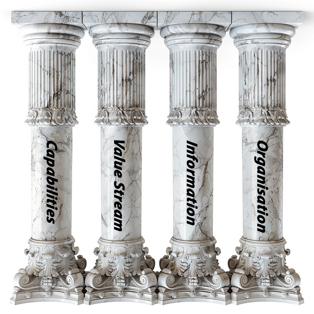
We do not see business processes appearing (directly) here. In this article, I want to elaborate on the relationship between business processes and enterprise architecture. I focus on Capabilities and Value Streams to show how business processes are part of the enterprise architecture.
I also want to show how processes work together with software, in cases where processes are executed wholly or partially automatically.
Business Processes and Value Streams
The metamodels and ArchiMate diagrams below are for version 4 of the ArchiMate standard.
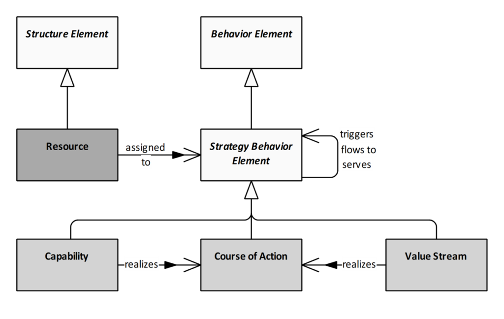
Processes have a direct relationship with the Value Streams they realize. This can be seen in ArchiMate’s classification model (commonly referred to as the ArchiMate metamodel). First, we specifically look at how ArchiMate views Value Streams and Capabilities, behavioural elements (behaviors) in the Strategy domain:
Processes are also behavioural elements, but in the Common Domain (the Process in the Common Domain meta model below):
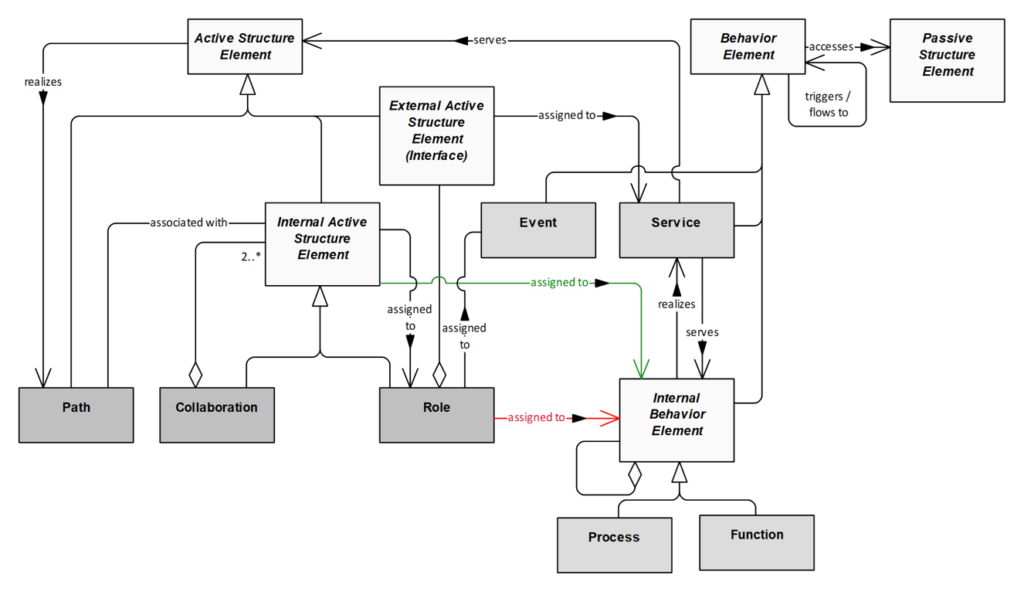
In the diagram below, you can see the relationship between the two. A Strategy Behavior Element can be a Capability or a Value Stream (see above), and a Process is an
Internal Behavior Element.
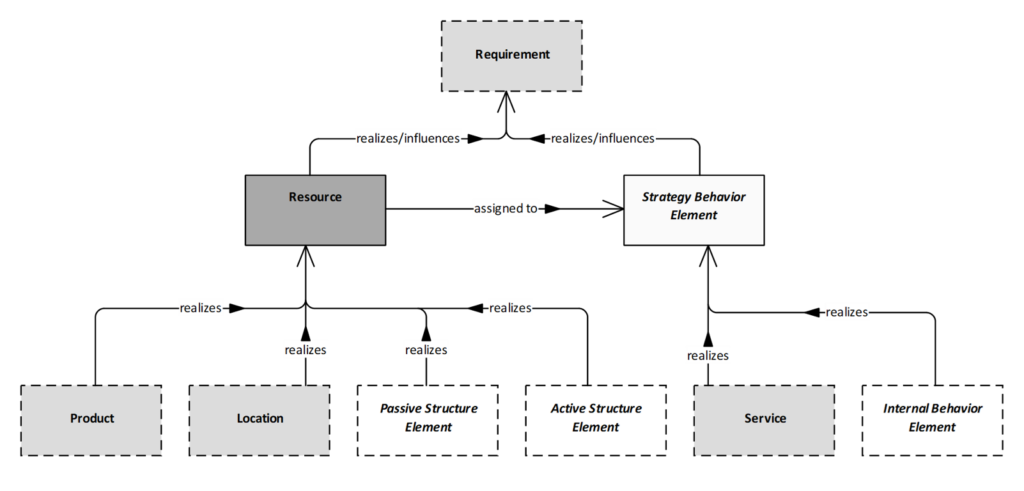
The relationship between a Process and a Value Stream is therefore a realization relationship. Below you see a simple example of how they can be connected. First, we look at the relationship between Capability and Process. Here I also immediately show the related BPMN version of the ArchiMate process.
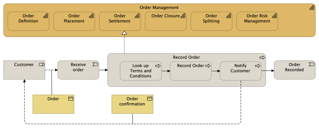
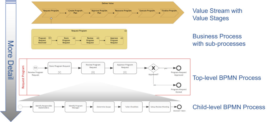
An example of a relationship between Value Streams and Process. This is also a Realisation relationship. In BPMN, it is subsequently possible to further hierarchically decompose the top-level process as far as necessary or meaningful. For this, I recommend the method of Bruce Silver as explained in his book Method & Style .
Repository
Ideally, both process descriptions are elaborated in the same architecture repository in a tool that supports both BPMN and ArchiMate (and preferably multiple other languages as well, particularly UML). The tool also assists in (hyper-)linking both models, so that it is evident that a process element in an ArchiMate view is the same as an activity in a BPMN view.
Now let’s go back to the abstract example shown in Diagram 1:
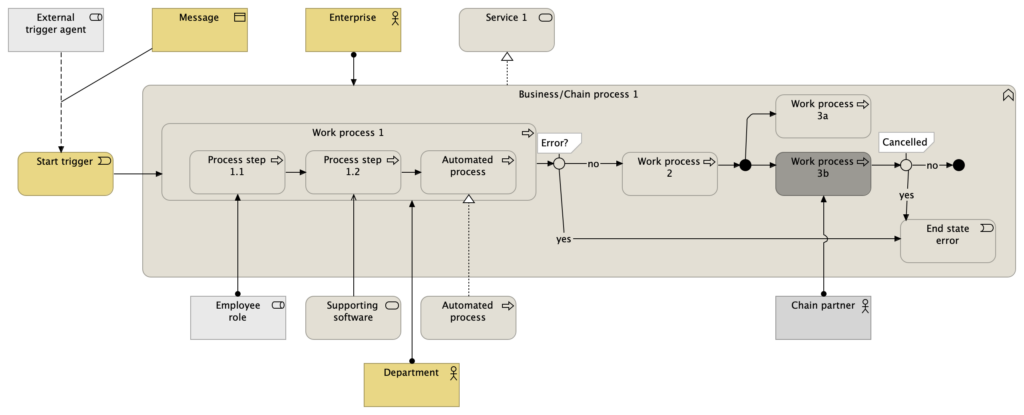
Below you now see that same process model, but now in ArchiMate. Note that for this strategy to work effectively we cannot avoid redundancy: the top levels of a process need to be modelled both in ArchiMate AND BPMN. Architects and business analysts interested in the details of a process can easily navigate from the high-level to the lowest levels this way.
Some observations
- From the enterprise architecture perspective, for every (business-) process we want to see which service that process provides: Service 1. This allows us to show in other views who the consumers/clients of that process are.
- We also want to record who is responsible for the process and who executes it. The distinction between Process and Work Process is intended precisely for this purpose: the process can have a person responsible for execution, while the work process has an executor (a department or a team). You can see this in the elements Business and Department 1, and the relationships (assignment) they have with the process elements. This is related to the Organization pillar .
- We also want to have insight into the applications used. Any software used is recorded in the model (for example in the Automated process step, which uses an Application Service named Automated process). This is an example of a process step that is executed entirely by software.
- A process step where a human uses software is Process step 1.2, which uses Application Service 1.
- We recommend using only activities, exclusive gateways (~XOR Junction in ArchiMate), parallel gateways (XAND Junction in ArchiMate), and simple events in top-level processes, and therefore no more esoteric BPMN concepts such as event-based gateways and complex event types. This is not to be enforced as a law, but more as a guideline to facilitate alignment.
- Finally, from an enterprise architecture perspective, it is essential to know which business objects are used where. This is related to the Information pillar .
In conclusion, I hope this explanation provides clarity on how processes should be modeled, especially under the NORA umbrella. I have successfully implemented this approach at both the Tax and Customs Administration and Defence.
Practical experience is crucial to further refine the approach, and for that reason, I invite readers to respond to my articles and engage in dialogue.